Visual Optimizations
When using AseptSoft, the visuals are very important, as you will read a lot of information through the colours of the components. The following commands will come useful when you want to easen the reading of the process in your existing P&ID:
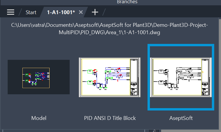
Dedicated Layout
It might come convenient to have a new AutoCAD Layout, to be used just for AseptSoft. This will allow you to adjust different layout settings, without affecting the actual P&ID.
Use the ASEPTSOFUTILSTLAYOUT command to automatically create such a layout
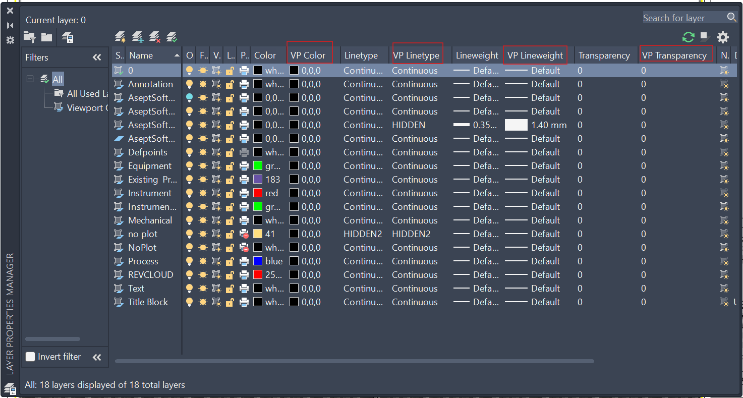
Using the AseptSoft layout, you will be able to benefit from the AutoCAD VP (ViewPort) Settings for the Layers, like custom VP Colours, custom VP Line weights, and custom VP patterns:
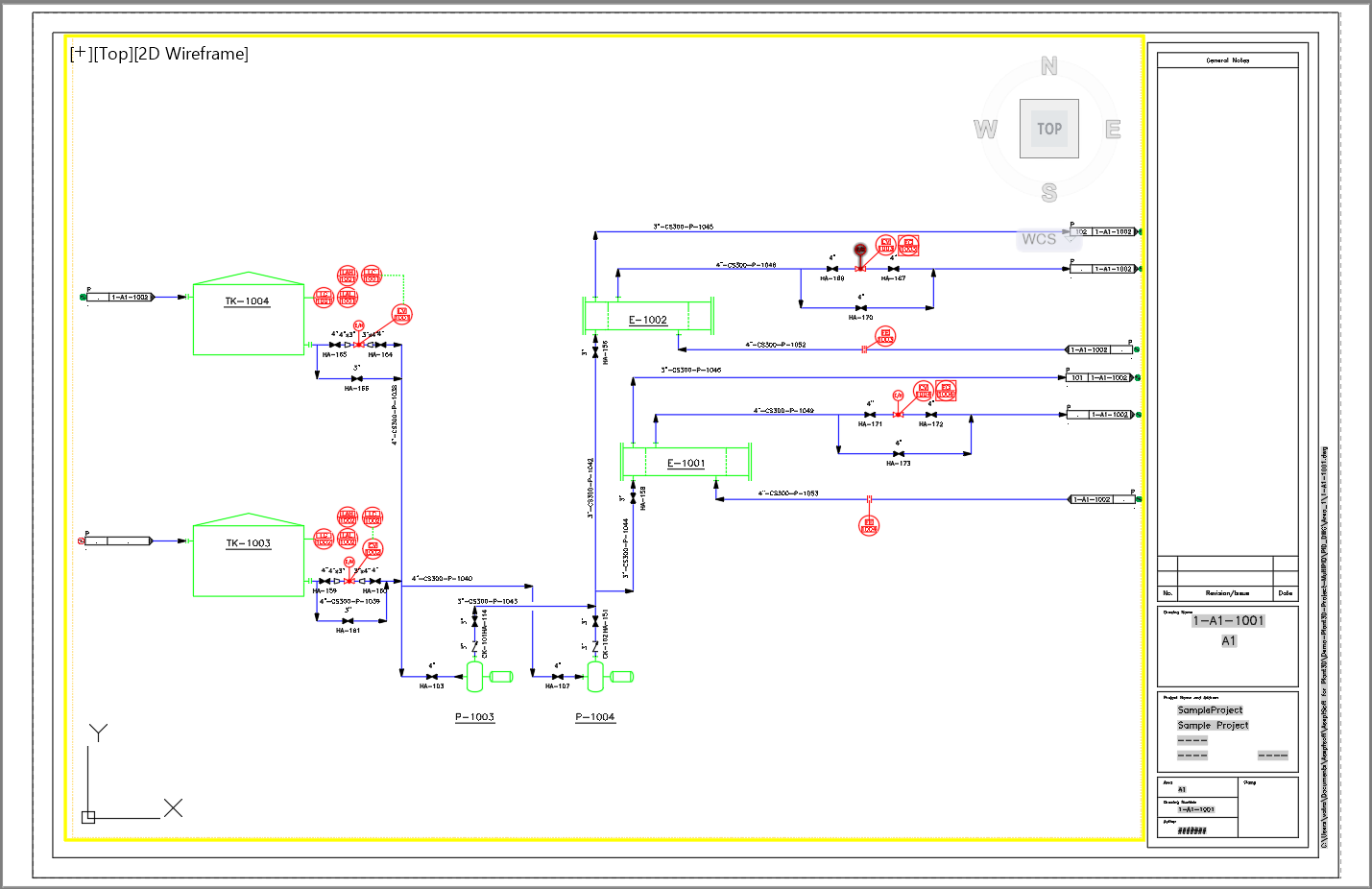
Black and White P&ID Layout
To visualise the AseptSoft colours the best, the P&ID should bring no colours if it’s own, as it will make it harder to see if an Engineering Item is coloured by AseptSoft in that colour, or is it just it’s normal colour. Also the pipes Fluidstream Simulations will be easier to read.
Hard to differentiate P&ID colours from AseptSoft colours

Easier to read see AseptSoft colours when the PID is black and white
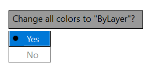
Use the ASEPTSOFTUTILSVPCOLOURS command to Automatically set the VP Colours of all Layers into a selected colour, and to assign “By Layer” colour to all geometries in the P&ID:
Colourable Engineering Items
Sometimes you will see that changing the State of an Engineering Item will not result in any visible colour change in the P&ID. This is due to the AutoCAD Block Definition. The Lines, Polylines, and other geometries that come into the definition of the Valve have their Colour set to something else than “By Block”.
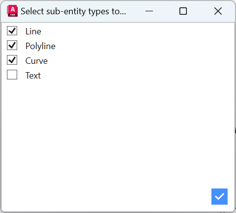
Use the ASEPTSOFTUTILSCOLOURABLESELECTION command to automatically change the colour of all lines within the Block Definitions to “By Block”. You will be asked to select the Blocks that you want to apply this change to, and then you will be asked to select the types of geometries that you want to change:
Fluidstream Simulations visibility optimizations
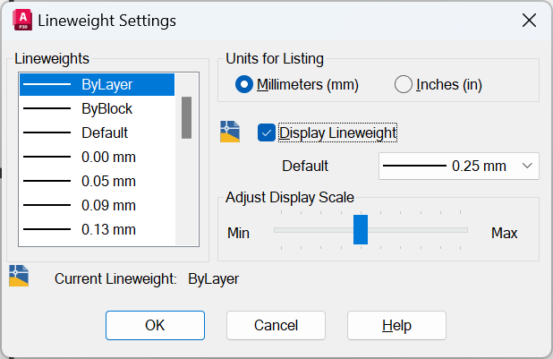
The Fluidstream might look better when you enable the Line Weight Display in AutoCAD using the LWEIGHT command. You will be prompted this window, where you can check the Display Lineweight checkbox.
Once you do so, you might want to set all the layers to use the default lineweight given by the previous window, and then only the AseptSoft FluidFlow Layer will get a thicker line:
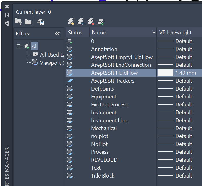
That will produce a clear and visible Fluidstream

Make sure that all geometries in the P&ID are following the Layer’s lineweight, and they will have the unified size.
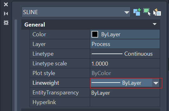
However, sometimes you will see that some blocks still don’t use the default lineweight value. This is due to the way the Block is defined in AutoCAD. The Lines, Polylines, and other geometries that come into the definition of the Block have their Lineweight set to something else than “By Layer” or “By Block”.
Use the ASEPTSOFTUTILSLINEWEIGHTSBYLAYER command to set the Lineweight for all the geometries within the selected blocks, to “By Layer”