State
Describes the appearance and functionality of an Engineering Item during a Phase when it uses this particular state.
The "open" state indicates that a valve is operational, shown in green, ensuring fluid flow from one side to the other. Similarly, the "filled water" state turns a tank blue, indicating water presence and potential contamination risk for connected components, essentially acting as a water source within the pipeline.
A state is defined by the following fields:
Name
Usage specifies the category of engineering items this state is designed for
Color
Fluid Response defines the behavior of the engineering item regarding the fluidstream simulations. More information in the Fluidstream Simulations.
Percentual specifies whether this state can have varying levels of activation. For instance, the state 'open percentual' can be expressed in percentages, such as a valve being 23% open. Similarly, the tank state 'filled with water' can also be represented in percentages, like a tank being filled to 45% capacity with water.
The next fields must be defined only if the state is percentual. The behavior of an engineering component is determined by its state when it deviates from 100% capacity. For instance, a valve fully open at 100% permits fluid flow, at 50% it partially allows flow, and at 0% it obstructs flow. This is due to the fact that at 0%, the valve is effectively closed.Zero Percent State: AseptSoft will treat the engineering item at 0% of the current state as the provided Zero Percent State. Alternatively to setting this field, set the following fields.
The next fields must be defined only if the Zero Percent State field is not definedZero Percent Fluid Response represents the Fluid Response that the current state has when used at 0%. More information in the Fluidstream Simulations.
Percentual Color Gradient sets the color on 0% when using the right side color picker.
The collection of states can be edited in the States window:
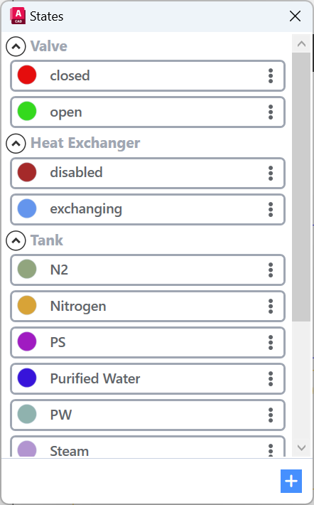
Right click any existing state to edit duplicate or delete it. To Create a new state use the ‘Create new’ button on the bottom.
When modifying an existing state, it is not possible to alter the Usage field. If you intend to make changes to this field, the original state must be deleted, and a new one created with identical properties but a different Usage.

Example Create
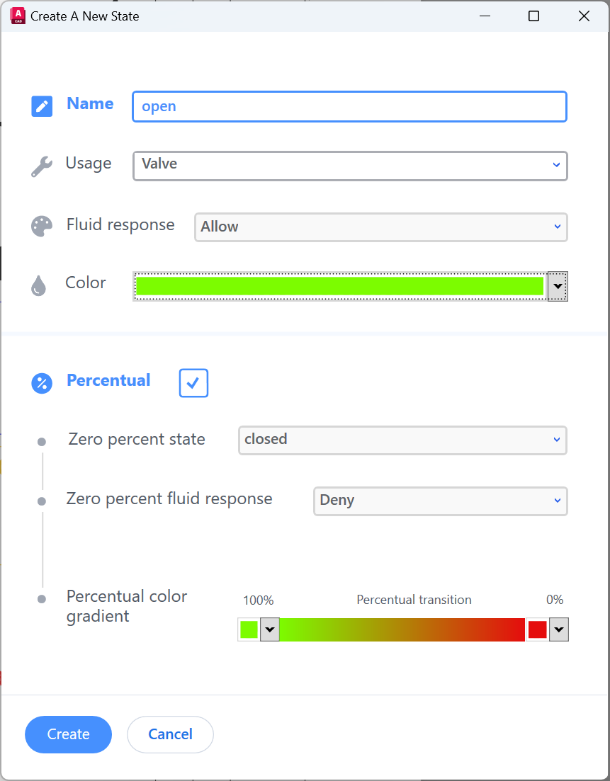
This state will be displayed Engineering Items labeled as 'Valve'. For further details on setting up Engineering Item Types, refer to the First time setup.
Custom Properties
After creation, open the same state for editing again, and you will see in the right side the special properties of the state:
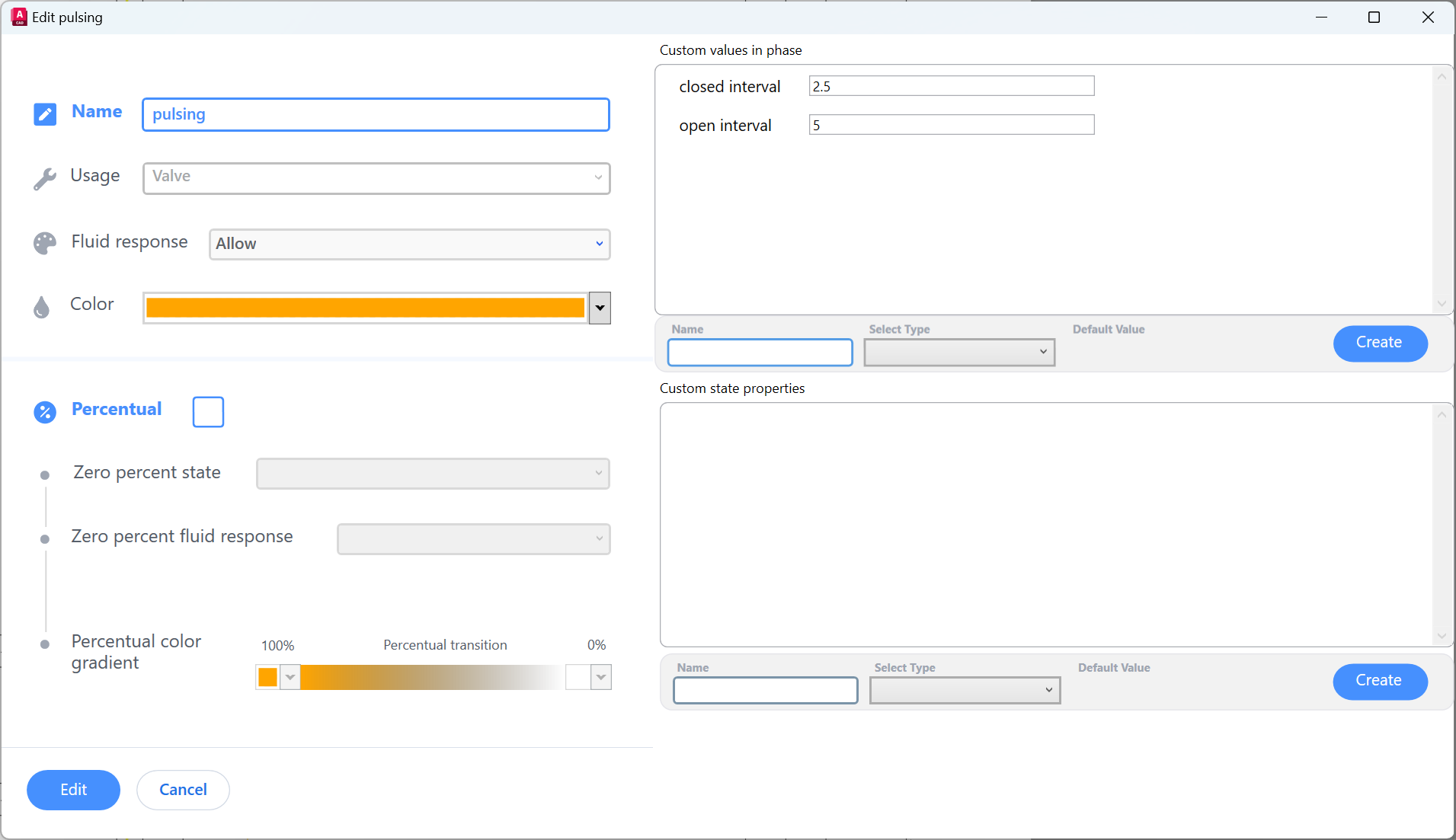
Custom values in phase
Defines properties that can have unique values for every Engineering Item in every phase.
Example: VP202 in phase 3 is pulsing at closed interval = 4, open interval = 2
VP202 in phase 4 is pulsing at a closed interval = 2, open interval = 3
The assignment of these values will be made through the Module Ribbon | Live-Edit.
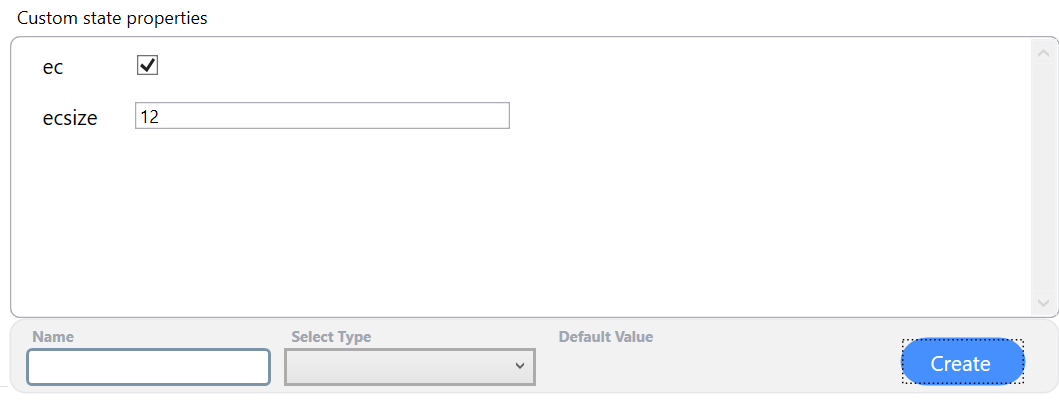
Custom state properties
Contains special values that you can use to control the process. They can be easily added and customized.
Currently the following special properties can be used, but more are available. In case you need any special properties, Contact us:
ec - type: true of false - if existing, only the states with the value True will display Connectors when clicked
ecsize - type: number of floating point number - if existing, defines how much smaller the Connectors will be displayed relative to the size of the parent EngineeringItem. 2 = half of the size of the parent. 4 = a quarter of the size of the parent.