Fluidstream Simulations
Overlays over your PID design tool to show where the fluid flow would go when starting from Source and Engineering Items like Tanks through the pipes and open valves.
It reads the geometry and the neighbourhood of the items in your PID to determine where the fluid advances through.
Fluidstream Simulations
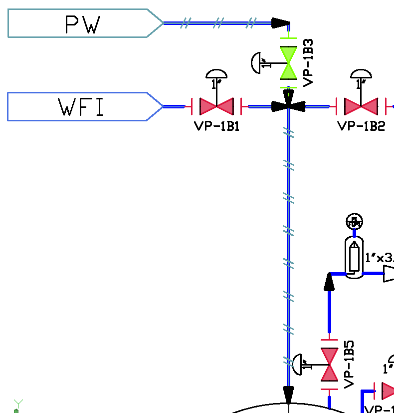
The Fluidstream simulate different fluids going through the pipes and the Engineering items of a PID and their Connectors. The fluids colour is defined by the Fluid, and while advancing, it colours everything that it touches. As in natural logic, the fluid will advance until it meets a closed item like a closed Valve. However, when one fluidstream will head into another stream, they will both stop at the meet point, and not mix up. Later on if any of the two streams is cut off, the other one will advance over the freshly emptied pipes and occupy them.
When facing an Engineering item, the State it activates in that specific Phase will determine the behaviour of the Fluidstream from that point ongoing.
The way pipes and Engineering Items connect to display the path of the fluid correctly, is described and can be customized from Fluidstream Simulations Mapping for AutoCAD, and from Fluidstream Simulations Mapping for AutoCAD Plant 3D
Fluid Response
Each Engineering Item has a Fluid Response at any moment. The following Fluid Responses are possible:
Allow causes the fluid to pass on to the engineering item as it is without affecting it.
Deny blocks the fluid to that specific component, and nothing goes further. If fluid is coming from two sides to an Engineering item, none of them will pass that Engineering Item
Unknown behaves just as ‘Allow’, but can generate warnings. Unknown will be automatically used when an Engineering Item has no active State, like a valve that has never been set to open or closed, so it remains gray as the PID created it. This is when the Unknown state becomes helpful, because having gray valves implies that you don’t want them to be part of your current process, and being reached by fluidstream is an unwished behavior, so the warning you get is making the work safer and more reliable.
Change into <Fluid> is primary used for filters. It works just as ‘Allow’ does, but changes the further fluid into the mentioned Fluid. Example: a filter receiving the Fluid ‘water’ will output on the other side ‘purified water’, which will advance further one as the current Fluidstream. When the filter does not receive water anymore, it stops the purified water stream.
Generates <Fluid> is primary used for tanks when they are filled. While activating such a state, the engineering item behaves as a fluid Source, and generates that fluid to all the neighbors in the PID. Example: a tank filled activating the state ‘water’ will constantly output the fluid with the same name ‘water’ as the active flow in all the directions. No matters if and what fluid comes towards a tank, the tank will output ‘water’ to all the other neighbors.
Engineering Items Fluid Response
The Fluid Response of an engineering item is determined by the active State and in some cases by the active Percent, by the following rules:
When a state does not activate any Percentage, it is equivalent to activating a percentage of 100%.
Example: simply saying that a valve is open is equivalent to saying that it is 100% open.
When the engineering item activates a state that is percentual, the following rules decide what is the Fluid Response:
Engineering Item’s Active Percent | Active State’s Fluid Response | Active State’s Zero Fluid Response | Engineering Item’s Fluid Response |
|---|---|---|---|
100% | anything | anything | the same as Active State’s Fluid Response |
1%-99% | Generate => priority 1 Change Into => priority 2 Unknown => priority 3 Allow => priority 4 Deny => priority 5 | Generate => priority 1 Change Into => priority 2 Unknown => priority 3 Allow => priority 4 Deny => priority 5 | the same as the one with the smaller priority number between the Active State’s Fluid Response and Zero Fluid response |
0% | anything | anything | the same as Active State’s Zero Fluid Response |
Example 1: the state ‘water’ has the Fluid Response=Generate Water, and the Zero Fluid Response=Allow, because a tank 0% filled with water is an empty tank, which does not generate any fluid but allows any incoming fluid to move further.
A tank activating the state ‘water’ on 100% has the Fluid Response ‘Generate Water’
A tank activating the state ‘water’ on any between 1% to 99% has the Fluid Response ‘Generate Water’
A tank activating the state ‘water’ on 0% has the Fluid Response ‘Allow’
Example 2: the state ‘open percentual’ has the Fluid Response=Allow, and the Zero Fluid Response=Deny, because a valve 0% open is an empty valve.
A valve activating the state ‘open percentual’ on 100% has the Fluid Response ‘Allow’
A valve activating the state ‘open percentual’ on any between 1% to 99% has the Fluid Response ‘Allow’
A valve activating the state ‘open percentual’ on 0% has the Fluid Response ‘Deny’
ConnectorsFluid Response
The Fluid Response of a Connector is determined by the active State and in some cases by the active Percent, as well as by the Output Pairs of the connector. See the Connectorspage for details about those properties.
A Connectors in Fluidstream Simulations behaves just as any Engineering Item regarding the active State and active Percent. it is considered to be a child element of an Engineering Item.
When an Engineering Item has visible Connectors, the Fluidstream Simulation logic will change such that when the fluid is entering the engineering item through one of it’s connectors, the fluid will be redirected further directly to the other connectors.
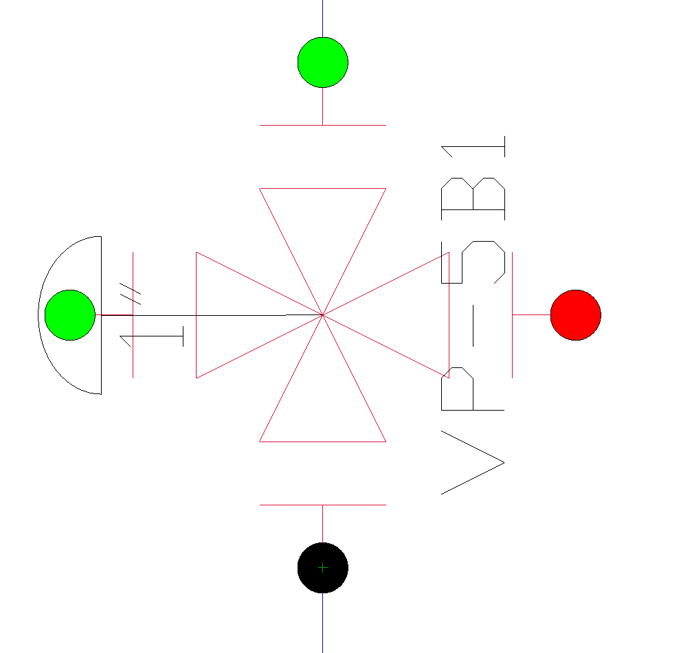
Output Pairs
Represent a list containing some, or all the other Connectors which can be found in the parent Engineering Item.
A connector will forward the incoming Fluid based on the Output Pairs property in the following ways:
If the fluid is coming from external Engineering Items, the incoming fluid will be forwarded to the Connectors of the parent Engineering Item which are mentioned in the Output Pairs list.
Example: A four way valve has 4 Connectors: Top, Bottom, Left, Right.
Top is Inward, and has all the other 3 connectors in it’s Output Pairs list
Bottom, Left and Right are Both, and only have Top in their Output Pairs list
Incoming fluid from a pipe towards Top will be forwarded to Left, Right and Bottom. It is up to the active State is Left Right and Bottom to decide on which of them the fluid will advance even further and where it gets blocked.
Incoming fluid from a pipe towards Left will be forwarded only to Top. But Top will block it as it is Inward, and fluid is only accepted to come and not to leave
Layers
Layers represent virtual spaces on which the shapes and the pipes lay, which overlay together to create the entire PID.
Example: The ‘Instrument’ layer will contain all the instruments of a PID
The Fluidstream Simulations are Layer-sensitive. That means the system has an awarness of where each shape lays on, and you can customize how you wish the fluidstream to interact with each layer
Restrict Layers
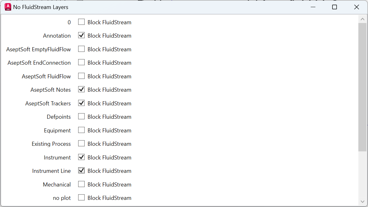
The following window can be used to determine which layers accept fluidstream simulations and which ones don’t. Once a layer does not accepts fluidstream simulations, fluid incoming to any shape or pipe laying on such a layer will not receive or forward any fluid.
Access this window from the Module Ribbon | Simulations panel.
AseptSoft will color only the Lines/Slines/Arcs which are connecting Assets or BlockRefferences. The colouring happens by duplicating each of these connector objects on the layer “AseptSoft FluidFlow” and “AseptSoft Empty FluidFlow”.
These lines are Temporary, and will be destroyed when the fluidstream ends.
While a temporary line is not touched by fluid, it lays on the AseptSoft Empty Fluid layer. When it is touched by any fluid, it moves to AseptSoft FluidFlow.
You can freely edit the properties of these layers (LineWeight, Pattern) to customize the estetics of the FluidStream.
Example
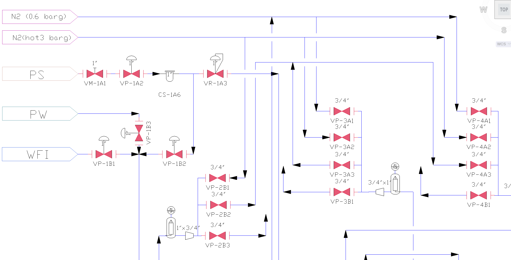
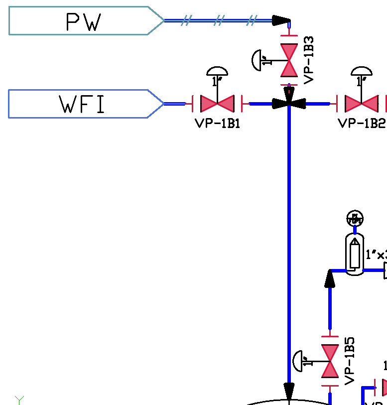
Fluidstream Disabled
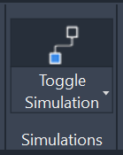
Use the ‘Toggle Simulations’ button in the project Ribbon to enable Fluidstream Simulations
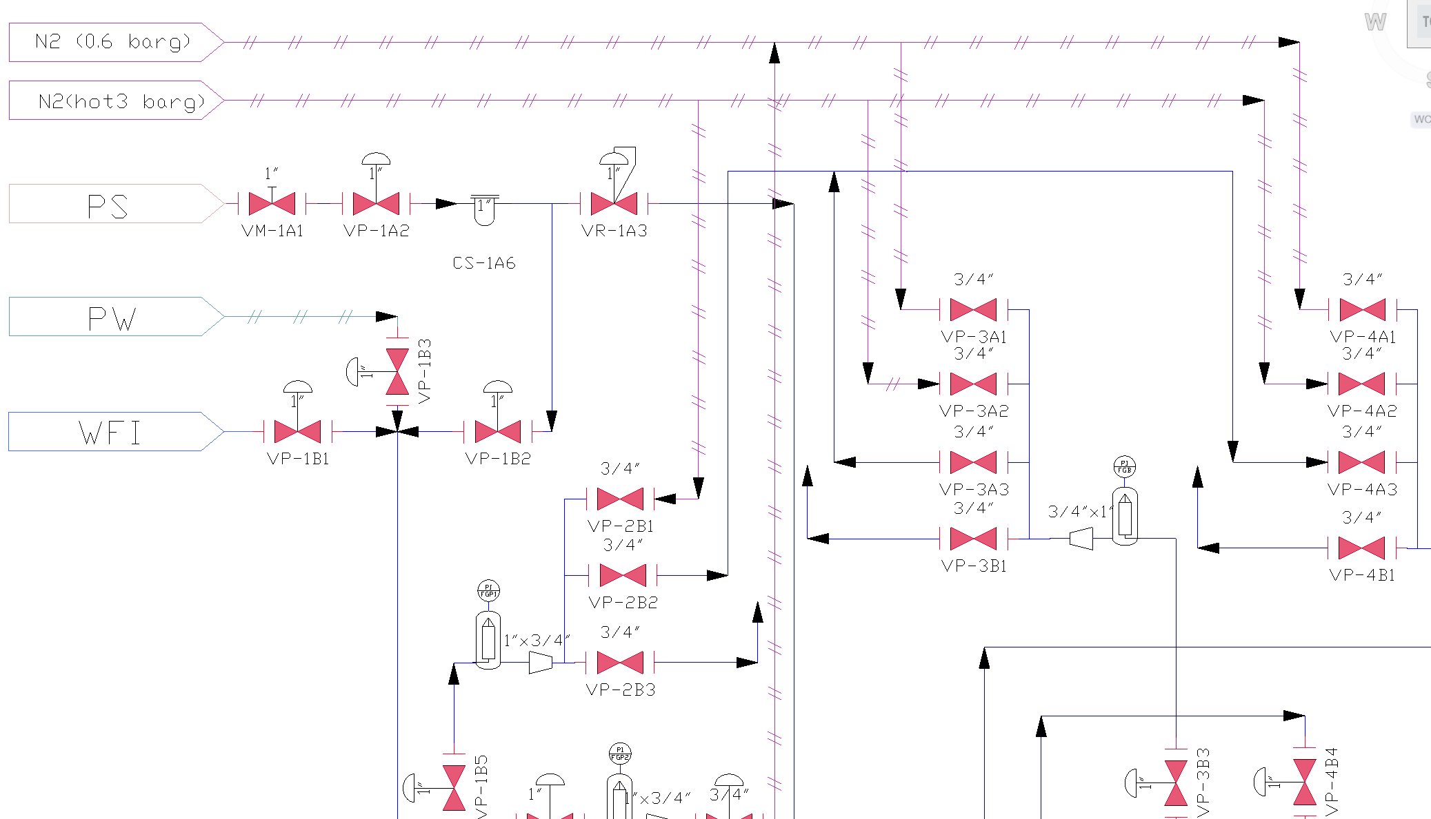
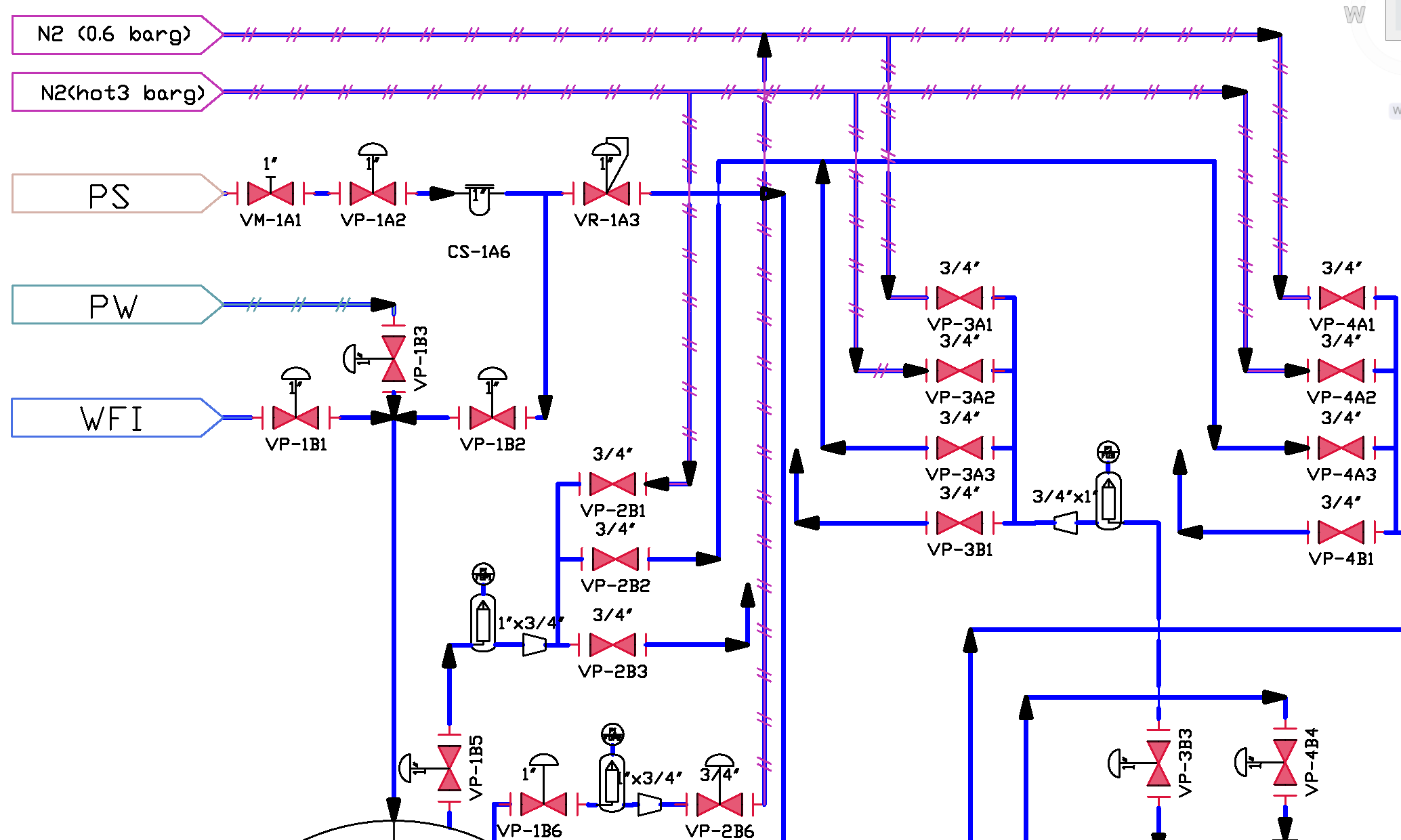
Fluidstream Enabled
Use the command ‘LWEIGHT’ and check the ‘Display Lineweight’ checkbox for improved visualisation (please reffer to Visual Optimizations for more details):
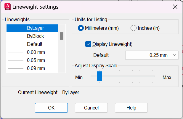
Display Lineweight
The fluidstream updates automatically to your changes:
