Class Types
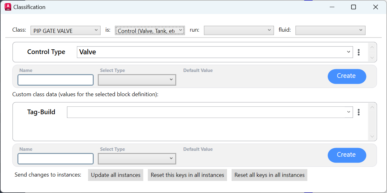
Control
Defines an Engineering Item. It uses the following Properties:
Control Type - not an actual Property Definition, but a standalone Attribute that defines what kind of Engineering Item this class represents (Valve, Tank, etc)
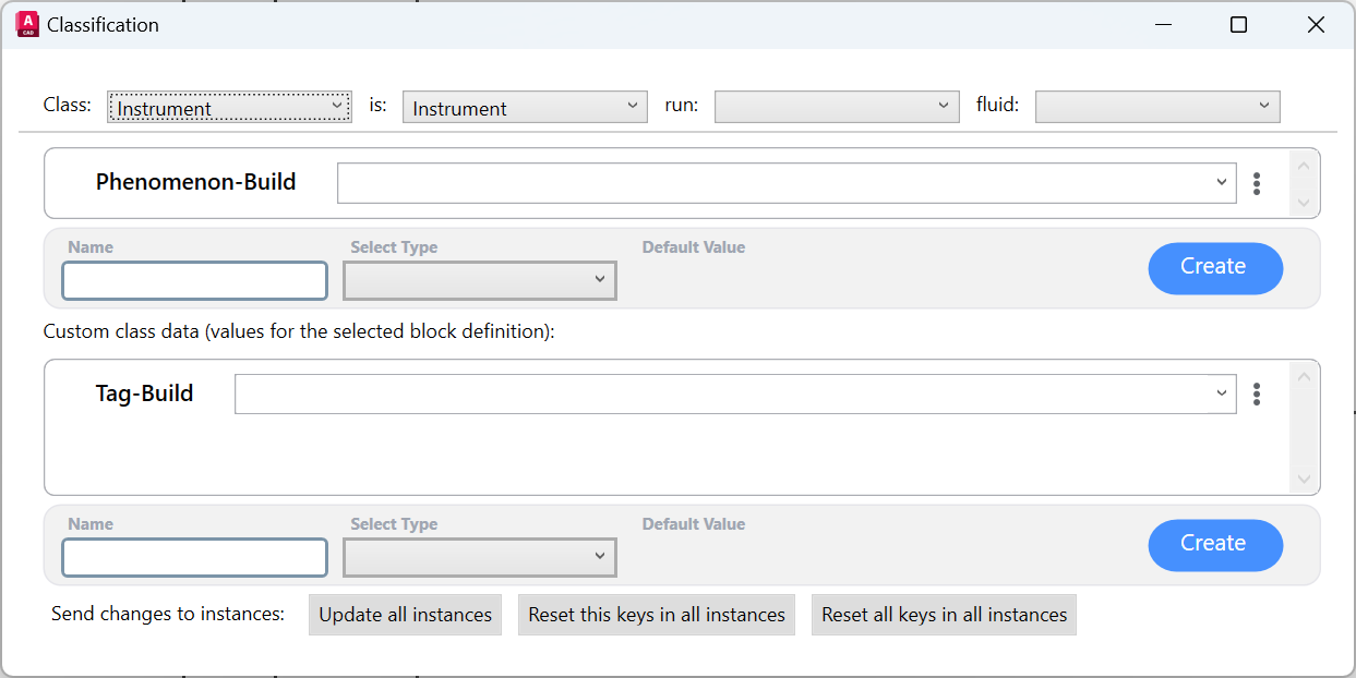
Instrument
Defines an Instrument. It uses the following Properties:
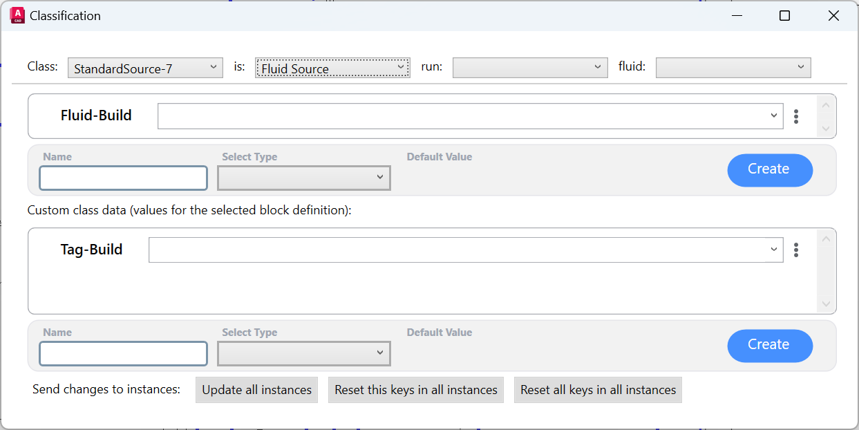
Fluid Source
Defines a Source. It uses the following Properties:
Off-Page Connector
Defines an Off-Page Connector. It uses the following Properties:
Off-Page Connectors that remain unbinded will behave as a Engineering Item of the type specified in the Control Type Attribute.
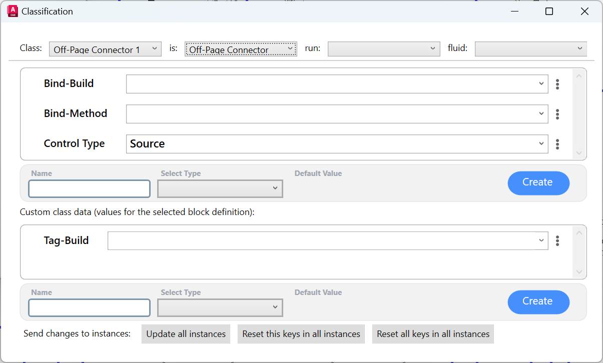
Note that the Properties Definitions | Bind property uses a few other Attributes than the standard ones:
Attribute | Description | Content |
|---|---|---|
Bind-Method Attribute(required) | Specifies wether the bind with another Off-Page Connector will happen when:
|  |
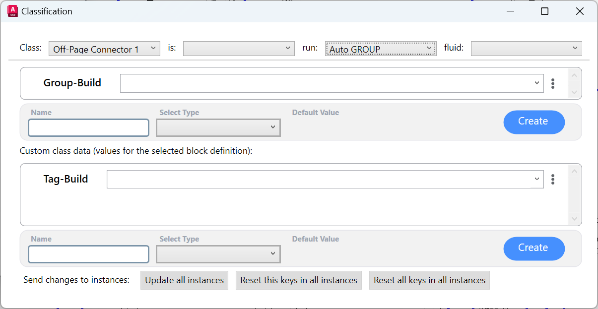
Auto GROUP
Defines a class whose Blocks will be automatically grouped with other Auto Group blocks that match the same Properties Definitions | Group value. It uses the following Properties:
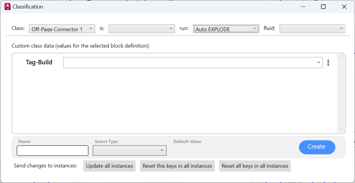
Auto EXPLODE
AseptSoft will automatically explode any Block whose class is set to Auto EXPLODE. This is useful for COMOS-Exported DWG files, where the Pipes are not lines where the Fluidstream Simulations can flow naturally, but rather solid Block References. To resolve that, the Class Grouping must be performed to group all the pipes into one Group, and then assign this Auto EXPLODE class to the group.
Area marker
Defines a class whose Blocks are used to split the P&ID in Areas with given names. Each other Block within the P&ID will fall under one of the areas defined by these classes, and they can use the area they fall into for their own Properties Definitions using the Non-Seeking Tokens | Area Token.
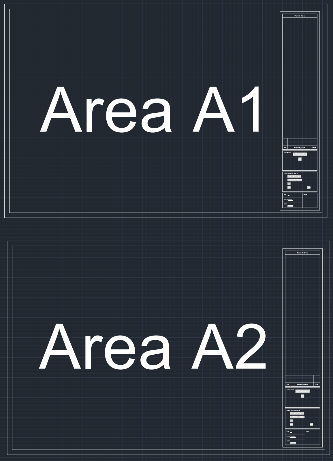
One Drawing with 2 Areas

The Area marker Block
If a DWG has two of the following Blocks,

Area marker Block Contains the Value for the Area A1
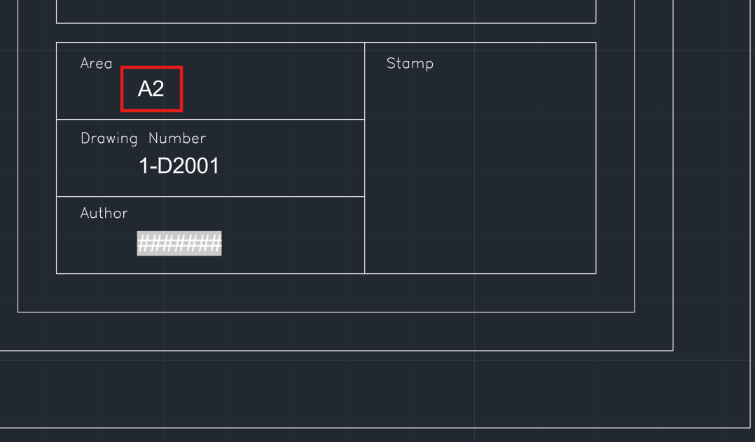
Area marker Block Contains the Value for the Area A2
The Area marker class uses the following Properties:
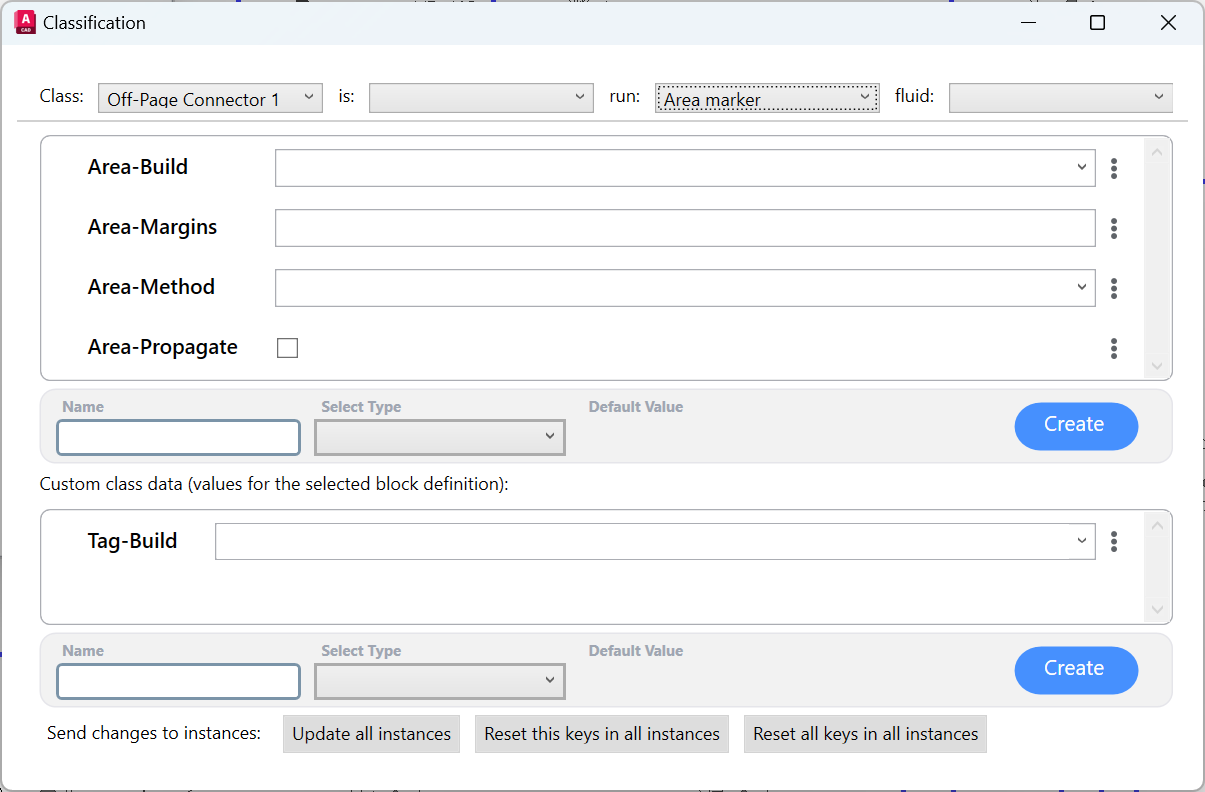
Note that the Properties Definitions | Area property uses a few other Attributes than the standard ones:
Attribute | Description | Content |
|---|---|---|
Area-Margins Attribute(optional) | It describes the aditional margin around the bounding box of the Block that will be included in the Area given by the Block. | Number written in local culture (point vs comma). Represents the AutoCAD distance in the current space (the same as the length of a line between the two points. |
Area-Method Attribute(required) | Specifies wether the Area will be assigned only to a particular part of the drawing, or to the entire P&ID |  |
Area-Propagate | Specifies wether the Area will propagate through he Fluidstream Simulations Mapping from object to object. | Checked or unchecked |
